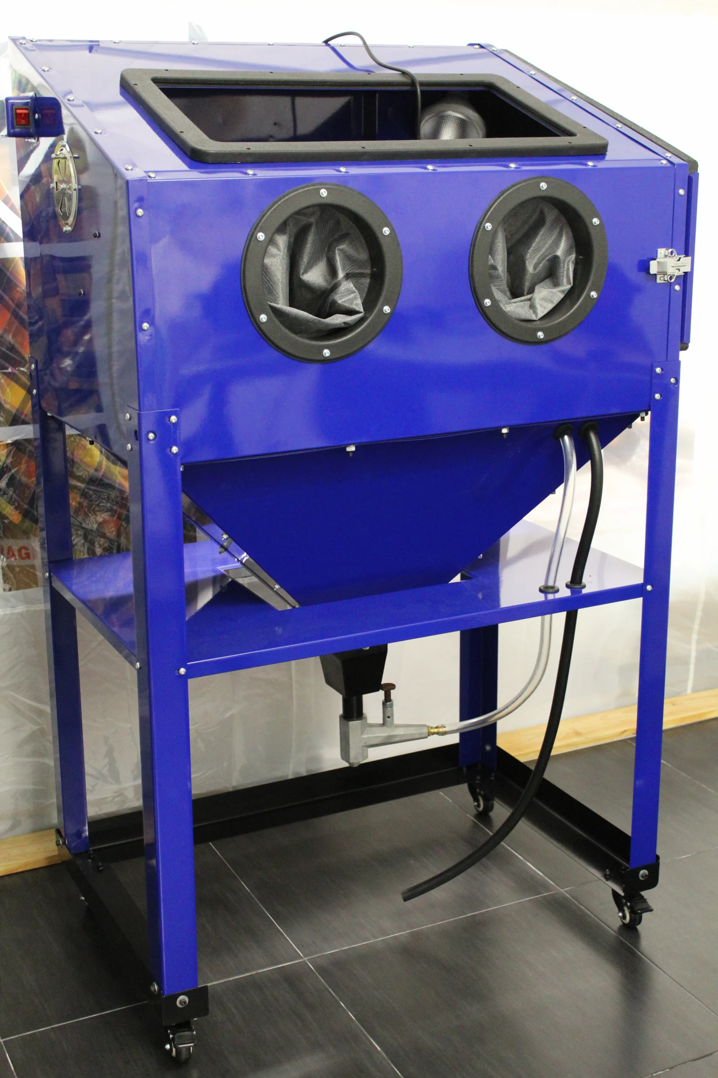
I’ve had this thing for 4 or 5 years now and it wasn’t until a few weeks ago that I opened the 2 boxes that make up this blast cabinet. Yes, it’s the same as the 40lb Harbor Freight sandblaster, just in navy blue. Maybe cobalt blue. Or azure blue, I don’t know, you decide. I’m not that good with colors.
This is not my first blast cabinet, I had a smaller one that I offered to a friend – yes, I’m that good of a friend – when I purchased this and since then I’ve been missing from time to time. It was far from being correctly set up, but it was usable when needed. The major issue it had was the flat bottom – the media from the gun accumulated at the opposite corners of the pickup tube and then I would have to lift one of the sides to push all the media to the other side so the pickup tube would get some media. At one point I had it at an angle and it still wouldn’t work right. After a few minutes blasting it would get tiring. Another problem was that I didn’t run it under vacuum, so the thing looked like a blowfish. I couldn’t see anything inside through the glass and everything around it would get covered in dust. Maybe it didn’t work so well.
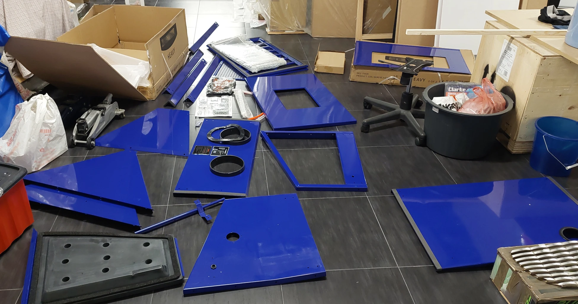
But now I have a better one, I just need to put it together. Oh, and buy an air compressor.
This post will be part 1 of 2 where I show my take on how to, hopefully, make this cabinet better than the one I used to have. The following modifications I’m about to show were mostly observed online on other people’s cabinets. I didn’t invent them, I’m only making the upgrades that make sense to me and if possible, improve on them. Like I said, my take.
REVERSING THE AIR FLOW
The first thing to address was reversing the air flow suggested by the manufacturer. They say fresh air should go in from the back and sucked (typically by a vacuum cleaner) from the side. Nothing wrong with that, but there’s a better way.
In my other cabinet that didn’t have any exhaust or intake ports, I would have a huge cloud of dust in just a couple of seconds after pushing the trigger of the gun. I’m pretty sure that if we have a vacuum cleaner sucking from an unrestricted port on the side panel of the cabinet, we end up loosing lots of media into the vacuum cleaner.
We can improve on this by reversing the air flow. The idea here is to have fresh air coming in from the side and connect the vacuum cleaner to the back of the cabinet. The new exhaust port will be behind the original baffle box and that will help ensuring the media is not sucked directly into the vacuum cleaner. Also, that port is up high, which means some of the media will fall due to its own weight and we’ll mostly be capturing air and very fine dust.
But in order to make this work we need to consider a few more things:
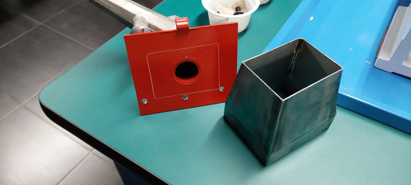
- The original baffle box welded to the rear panel is opened on both ends, top and bottom. We need to cover the top to ensure our vacuum cleaner is only pickup up from the bottom. I’ve done this with a 3D printed cap.
- We need an adapter for the vacuum cleaner. I designed and 3D printed one, then bolted it to the rear panel using rivnuts.
- Our new intake port is now open and we need a way to avoid having media shot directly into it. That can be done with a new baffle box. I’ve done this out of sheet metal. Reason: fine dust will slide off better from sheet metal than a 3D printed object.
- To try and regulate the vacuum inside the cabinet I’ve added a barbecue vent to the inlet. If needed, I’ll be able to regulate the vacuum cleaner we well.


SEALING THE CABINET
I started to mount the top and hopper keeping the foam tape that came glued to each panel, but then I changed my mind and took it all apart to remove the tape. I used an heat gun to help removing the tape without leaving the glue on the panels. To seal both parts I used a paintable transparent sealant, first on the outside where all panels overlap and then on the inside where they join.
The reason to do this is because if there’s enough pressure inside the cabinet, it will leak and the foam will not be enough to prevent that. I believe that having all the seams caulked (with sealant from both sides) is a better approach.
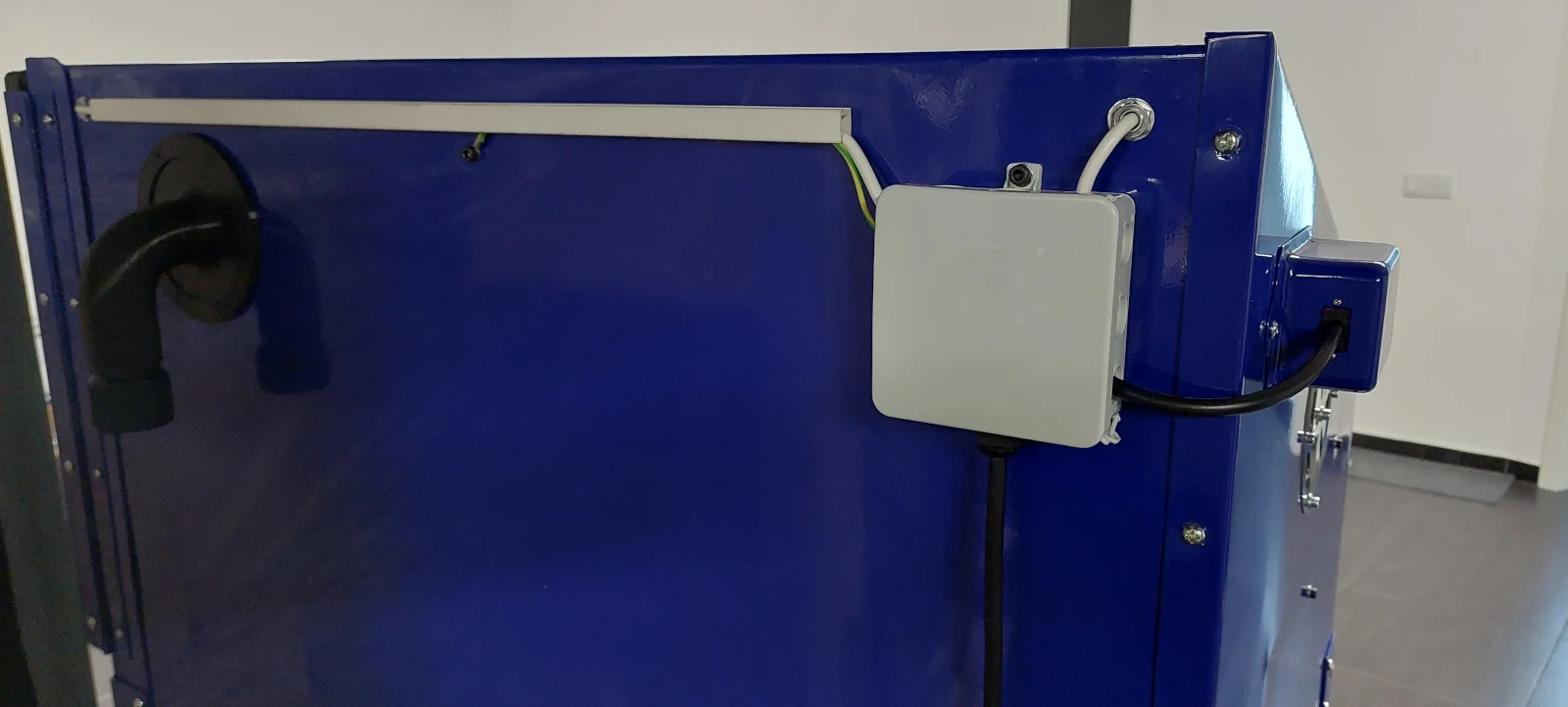
LIGHTING & ELECTRICS
My old cabinet didn’t have any light, well it did but the amount of dust flying was always so much that I never turned it on, so actually being able to see what I’m doing will be something new.
This cabinet came equiped with a 12V 3W LED light. It’s kind of a poor light, so I ditched that and replaced it with 2 flood lights, one mounted at each side. They are so much brighter. Wiring was very easy. I’ve bought a few shallow adjustable lamp sockets and the wires just run through them into a box mounted at the back of the cabinet. These sockets are actually quite important parts because they don’t take too much space and allow us to point the lights to where we want them. They also help sealing the cabinet as we don’t have to get extra holes for the wiring. As for the button to turn them on, I managed to keep the original switch housing and switch. Just kept it simple. I see a lot of people connecting the lights to the same switch for the vacuum, but that doesn’t make sense to me – why would you have the lights killed when you pause for a minute? I want to be able to see and check the progress without hearing the vacuum cleaner.
Next, I grounded the cabinet. Sometimes these things like to give static electrical shocks due to the static accumulated in the cabinet while we’re blasting. Then when we touch the gun or the blasted part that static will be discharged through our bodies – that’s how we get shocked. Having the cabinet grounded means I can use an ESD wrist strap attached to it. Having common ground with the cabinet will reduce / eliminate eventual shocks.


REPLACING THE PICKUP TUBE WITH A METERING VALVE
The original pickup tube is known to be inefficient. The benefits of replacing it with a metering valve is better control of how much media gets to the gun and being able to use a much smaller quantity of media inside the cabinet. This happens because the media shot by the gun will fall to the bottom and since we’re picking it up right from the bottom, the cycle goes on with less media needed.
This metering valve is a device that will get the media from the bottom of the cabinet and, due to the venturi effect, will allow that media / air mixture to be pulled from the other end, through the hose, back into the cabinet. This is easily built out of plumbing parts (it’s basically a pipe with an adjustable air source in the middle) and I’ve done just that. However, as time went by I started to look to how harsh each connection was and how that didn’t help the media to flow well. I ended up buying a proper metering valve from one of the sandblasting suppliers and it turned out not to be much more expensive than all the plumbing parts needed.
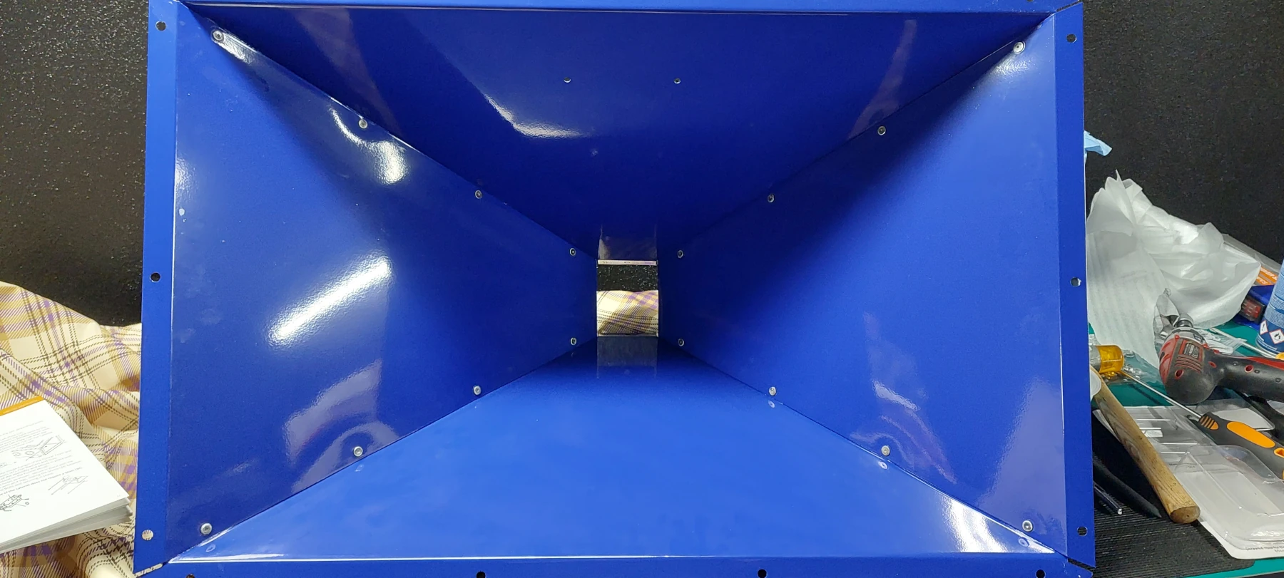
REPLACING THE HOPPER BOTTOM DOOR WITH A FUNNEL
The metering valve can be attached to the original bottom door for the hopper. However that same door is also a source of leaks. If we have a way to remove all the media through the metering valve we can eliminate the original door and replace it with a funnel. I made mine out of sheet metal, it’s not perfect, but I think it will work. Then I fitted it, caulked the seams and painted over them with 2K polyurethane paint. The paint is to help the media slide to the bottom.


MAKING IT MOVEABLE AND ADJUSTING ITS HEIGHT
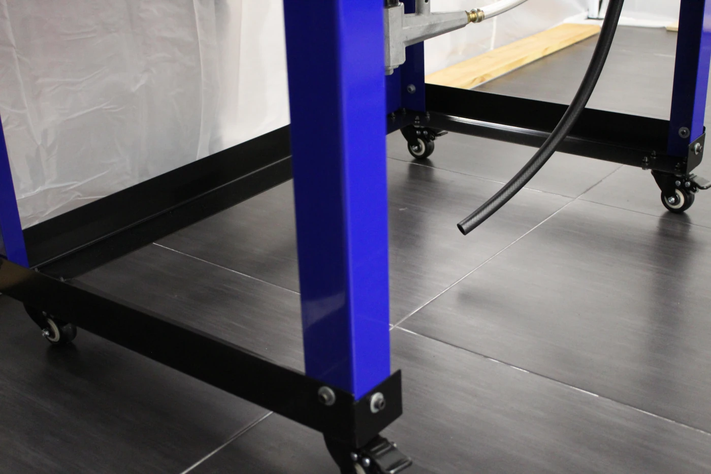
This is a 2 in 1. I need my cabinet to be moveable so I’m adding some wheels (locking casters). This is also the perfect timing to adjust it to the correct height when I’m using it. This is very specific to the person using the cabinet – we want to feel comfortable and not leaning to see what’s inside.
I tried a few ideas and settled with just some angled sheet metal welded together forming a large U shape. I tried to make a full cart, but I think it would get in the way when I’m blasting. Not only fighting it with my feet, but also using a foot pedal means I’d be in a very awkward position. The U shape does not get in the way and I can even add a small tray if I want to in the future.
LOWERING AND REDUCING THE SIZE OF THE TRAY
I wasn’t sure about this modification and I thought I wouldn’t do it as there wasn’t really a need for it. But then I realized it just made sense.
Having the meter valve on the bottom of the hopper means the hose for the media is now coming from the outside of the cabinet and at some point, it needs to get inside it. We can drill a hole next to the air connector hole, below the door, but that would make our hose make an awful turn and kink. It makes sense to enter the cabinet from the bottom. Same thing for our foot pedal hose.
So while we could have both holes drilled on the front of the hopper and then through the tray, it’s quite possible we would end up fighting the hoses getting stuck when we try to blast. Lowering the tray and having the hoses coming up from the top is the cleaner solution.
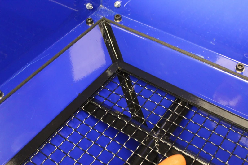
To lower the tray we can discard the reinforcement part that goes underneath it – it’s really not needed in most cases and it’s one less leaking point between the hopper and the cabinet. Then we cut the sides from the mesh grille, cut the mesh and refit the sides again. It’s a bit of work, but easy enough.
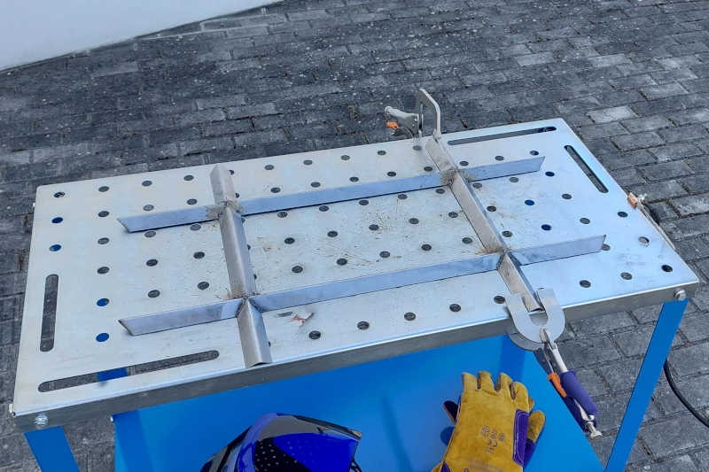
Since I plan on blasting some heavy parts, I thought that having a reinforcement was actually important, so I made my own. It just sits on the hopper.
And that’s it for now. I hope to be able to finish this cabinet soon and post here Part 2 of this build.